View Images Library Photos and Pictures. 3 Logic Circuits Boolean Algebra And Truth Tables Dr Stienecker S Site Answered Below Picture Shows The Composite Wall Bartleby Lessons In Electric Circuits Volume I Dc Chapter 5 Answered 4 Sketch The Output Waveform Of The Bartleby

. 3 Draw The Schematic Diagram Given The Figures Belowfigure A Brainly Ph Solved Figure 4 51 Is A Schematic Diagram Of An Aircraft Elevator Control 1 Answer Transtutors 10 Simple Online Drawing Tools For Effective Thesis Diagrams Ilovephd
Homework 5 With Solutions Homework Eecs 31 Cse 31 Ics 151 Daniel D Gajski S Web Site
Homework 5 With Solutions Homework Eecs 31 Cse 31 Ics 151 Daniel D Gajski S Web Site
 3 Logic Circuits Boolean Algebra And Truth Tables Dr Stienecker S Site
 Design Handbook Engineering Drawing And Sketching Related Resources Design And Manufacturing I Mechanical Engineering Mit Opencourseware
 Solved 8 82 Figure P8 82 Shows The Schematic Diagram Of A Cogeneration 1 Answer Transtutors
 Resistors In Series And Parallel Physics
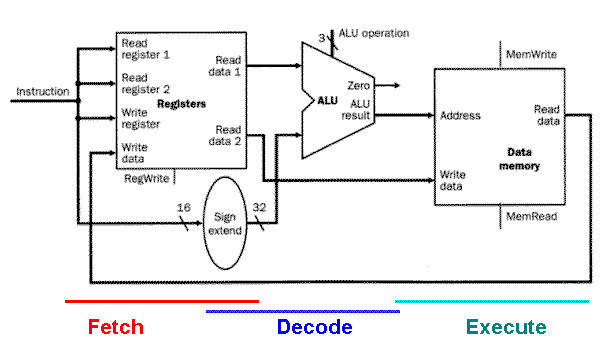 Organization Of Computer Systems Processor Datapath
 Example 12 8 In The Circuit Diagram Given In Fig 12 10 Suppose The
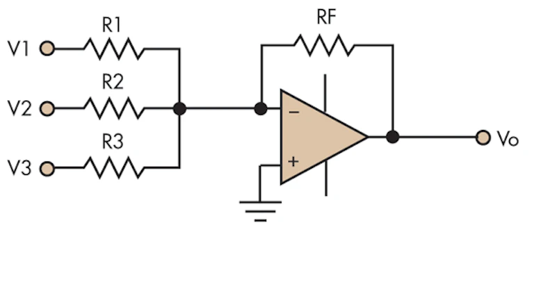 Efficiently Design An Op Amp Summer Circuit Electronic Design
 21 1 Resistors In Series And Parallel College Physics Openstax
 Ohm S Law Electric Circuits Siyavula
 3 4 Draw The Schematic Diagram Given The Figures Below Brainly Ph
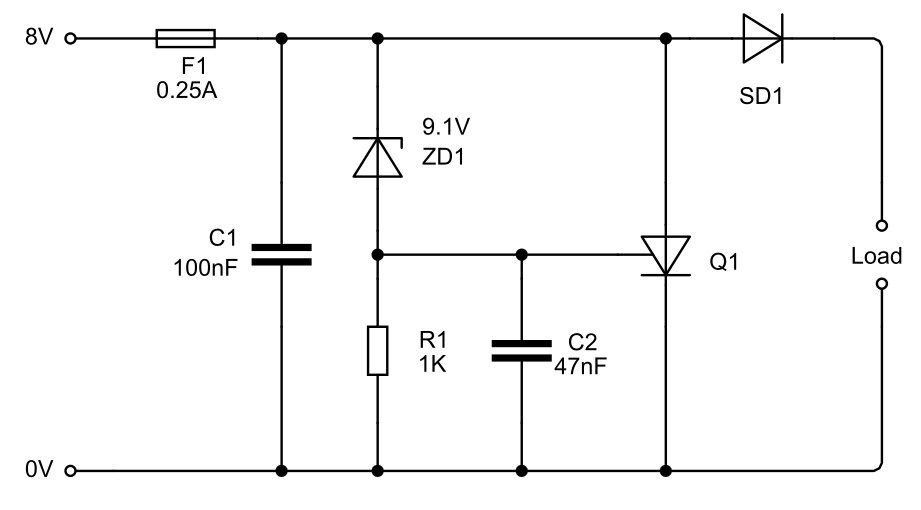 Understanding Schematics Technical Articles
 Stm32 Usb Spi Flash Simple U Disk Design Programmer Sought
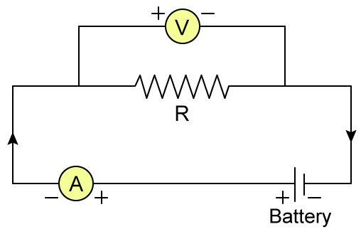 State Ohms Law Draw A Circuit Diagram To Verify Ohms Law Physics Topperlearning Com T87tbuzz
Physics Tutorial Circuit Symbols And Circuit Diagrams
State Tables And State Diagrams
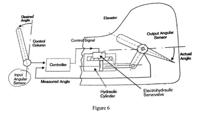 Figure 6 Below Gives The Schematic Diagram Of An A Chegg Com
 Lakhmir Singh Physics Class 10 Solutions For Chapter 1 Electricity Free Pdf
 Current Through Resistor In Parallel Worked Example Video Khan Academy
 Figure Below Shows A Section Of A House Wiring System I Name I The Circuit Labelled F Ii The Terminals A And B Ii Give A Reason Why
With The Help Of A Diagram Derive The Formula For The Resultant Resistance Of Three Resistors Connected In Series Studyrankersonline
 A Circuit Is Shown In The Diagram Given Below A Find The Value Of R B Find The Science Electricity 9455821 Meritnation Com
 Solved Consider The Counter Circuit Shown In The Figure Below The Coun Self Study 365
 The Schematic Diagram A Basic Element Of Circuit Design Analog Devices
 Draw A Circuit Diagram For The Figure Below Chegg Com
 Draw The Circuit Diagram To Represent The Circuit Shown In Figure Science Shaalaa Com



No hay comentarios:
Publicar un comentario